Solar Designer Secrets: TMG Reveals All
If you ever wondered how solar designers designed the solar panel arrays you see on so many rooftops nowadays, this article tells it all.
The solar designer needs these inputs about the target site to start on a design project:
- A dimensioned view of the roof
- Dimensioned locations of protuberances like vent pipes and chimneys
- Rough positions of the proposed solar panel arrays
- The make and model number of the solar modules to use
- The expected power output of the system
- Information about rafter width and spacing
- Preferred locations for supporting components such as the sunrun meter, the load center and the inverters
THE PROCESS
The solar designer then performs the following steps:
1. He decides where to place the arrays. This can be broken down into several subordinate activities:
a) He drafts the roof to scale, and incorporate all the protuberances at their exact locations (if the drawing looks cluttered, he drafts a callout view for individual roof slopes)
b) He chooses slopes which will have maximum exposure to the sun during summer and winter. This is usually a South-facing slope. He could also choose the East or West-facing slopes, but there would be a small loss in efficiency when compared to arrays mounted on the South-facing slope.
c) He tries to avoid locating the arrays on a North-facing slope since there is considerable loss of efficiency in doing this.
d) He also considers shadows from tall elements (like trees) adjacent to the proposed installation and avoid placing arrays in them.
NOTE: Usually the site engineer provides a sun study, and simply following his recommendation for the proposed location and orientation of modules is enough to satisfy the above conditions.
Solar modules can be divided into two types, DC and AC. Multiple modules are assembled into arrays on metal frames. These arrays are called strings in the case of DC modules and branches in the case of AC modules.
e) A string can have between 7 and 12 modules per array, whereas a branch can have between 8 and 15 modules.
f) Within an array, we ensure modules have around 1” clearance between them in the horizontal direction and around 3” clearance in the vertical direction (this may differ with respect to the make and model of solar modules used).
g) The solar designer positions arrays on the roof with sufficient clearance from the ridges, eaves and other edges of the roof. 12” is usually enough, but this can differ depending on the make and model of modules and the mounts used.
h) After orienting the solar modules, the solar designer locates and plots the position of the attachment points on the roof, and defines the attachment mounts that have to be used. He positions the attachment points on the roof to be located on the centers of rafters. Normally the solar designer positions them at 48″ O.C.
NOTE: There are different types of attachment mounts the designer can use; the choice depends on the type of roof. For instance, he would use “Flatjack” for composite shingle roofs and “Fastjack” for virtually any roof that requires a flashed install.
The solar designer estimates the location of the rafters by offsetting a line 24″ from the right or left edge of the roof, then offsetting multiple lines at distances of 48″ till the end of the roof.
He takes care not to position a module on a single attachment point and not to let the unsupported edge of a module be more than 16″.
The solar designer takes into account the load-bearing capacity of attachment mounts when deciding the total number of attachment mounts needed to support an array.
2. The next step is to draft the electrical connections from the solar arrays to their electrical support components, including the metering panel.
For this, the solar designer finds the shortest route (avoiding diagonal crossings that create unpleasant aesthetics) on the roof and draws a single line to connect the arrays to a junction box, then on to the sunrun meter, inverter, load center and metering panel. He also follows any special instructions that our installer-customers had noted on the site survey document.
The solar designer places the junction boxes at a convenient location near the modules and in such a manner as to use a minimum length of wire from each string or branch. He ensures there is sufficient clearance around the sunrun meter, load center and inverter for easy service access.
He adds an earth electrode to the drawing if it doesn’t exist near the metering panel.
THE RESULTING DRAWING SHEET SET
A typical design sheet set consists of:
An index page drawing containing:
- A site plan showing roads adjacent to the site
- A satellite view (in color) of the site
- A map view showing the adjacent areas
A second sheet containing:
- A dimensioned roof plan showing the locations of the solar arrays and attachment points
- An attachment detail
- A GA drawing of the electrical metering area
A third sheet containing:
- An electrical schematic
- Instructions for signage
- A materials list
- Notes
(A placard layout may also be needed to conform to local laws)
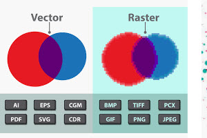
All the above sheets are converted to PDF format for the convenience of users who do not have access to or expertise in the specialized CAD software used to create all the above sheets.
IN CONCLUSION:
As in the case of any seemingly complex activity, solar design is easy to perform if one has procedural knowledge and ample experience. (TMG, of course, possesses these qualifications. If you are interested in sampling TMG’s design capabilities, please go to our solar designer page.)
To your excellent solar design,

Technorati Tags: solar designer,solar desugn,pv design,solar engineer,cad services,drafting services